What Is a Fiberglass Structural Shapes Chart?
A fiberglass structural shapes chart is a comprehensive reference table listing standard sizes, dimensions, wall thicknesses, and section properties for pultruded fiberglass profiles. These charts are essential tools for engineers and specifiers working with FRP I-beams, channels, angles, and tubes in construction, industrial, and infrastructure projects. Each entry in the chart provides dimensional measurements, weight per foot, moment of inertia, and section modulus.
Unlike steel or aluminum, fiberglass structural shapes offer corrosion resistance, electrical insulation, and high strength-to-weight ratios. The chart allows you to quickly compare profiles and select the right shape for your load-bearing application. This guide provides a complete reference to understanding and using these charts for your next project.
Types of Pultruded Fiberglass Structural Shapes
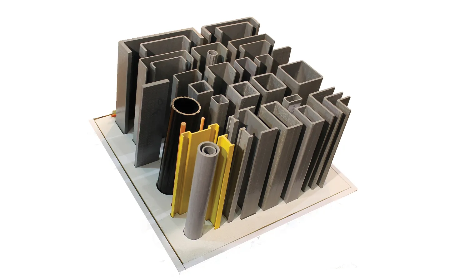
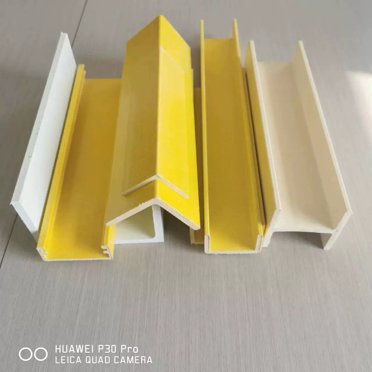
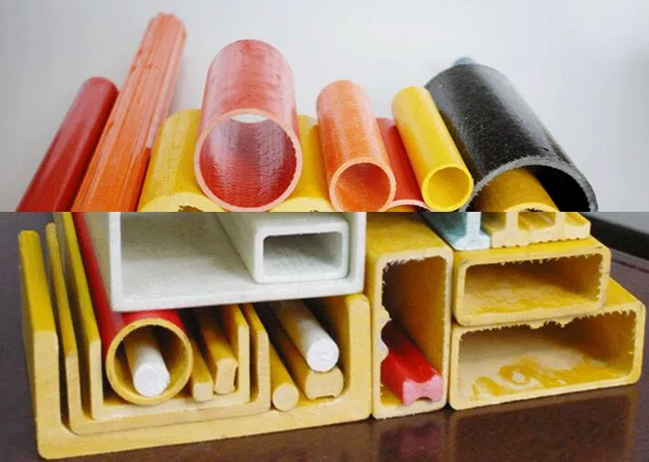
Pultruded fiberglass structural shapes are manufactured through a continuous pultrusion process where glass fibers are impregnated with thermosetting resin and pulled through a heated die. This creates profiles with consistent cross-sections, high strength, and excellent dimensional stability. The most common shapes include I-beams, channels, angles, and tubes.
Fiberglass I-Beams
Fiberglass I-beams are the most widely used structural shape for primary load-bearing applications. They feature a vertical web with horizontal flanges on top and bottom, providing excellent resistance to bending and shear forces. Standard sizes range from 3 inches to 24 inches in depth, with flange widths proportional to the beam depth. These beams are commonly used in building frames, walkways, platforms, and equipment supports.
Fiberglass Channels
Fiberglass channels (C-channels) have a U-shaped cross-section with a web and two flanges on the same side. They are ideal for edge-to-edge connections, framing members, and bracing applications. Channels are often used as stringers for grating support, railings, and cable tray systems. Standard sizes typically range from 2 inches to 12 inches in depth.
Fiberglass Angles
Fiberglass angles (L-shapes) consist of two legs meeting at a 90-degree angle. They are used for bracing, corner connections, stiffeners, and light structural framing. Equal-leg angles are most common, with leg lengths from 1 inch to 8 inches. Unequal-leg angles are also available for specific design requirements.
Fiberglass Tubes and Square Profiles
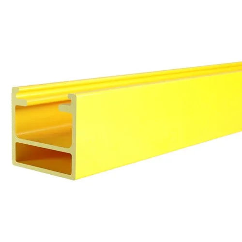
Fiberglass tubes are available in round, square, and rectangular cross-sections. Round tubes are used for handrails, columns, and piping supports. Square and rectangular tubes serve as posts, columns, and framework members in corrosive environments. Wall thicknesses typically range from 1/8 inch to 3/8 inch depending on the profile size.
Standard Fiberglass Structural Shapes Sizes and Dimensions
A fiberglass structural shapes sizes and dimensions chart provides the nominal dimensions for every standard profile. These tables typically include the overall height, flange width, web thickness, flange thickness, and weight per linear foot. Below are the standard sizes for the most common fiberglass structural shapes.
Fiberglass I-Beam Size Chart
| Beam Depth (in) | Flange Width (in) | Web Thickness (in) | Flange Thickness (in) | Weight (lb/ft) |
|---|---|---|---|---|
| 3 x 1.5 | 1.50 | 0.19 | 0.19 | 1.02 |
| 4 x 2.0 | 2.00 | 0.19 | 0.25 | 1.65 |
| 5 x 2.5 | 2.50 | 0.25 | 0.25 | 2.44 |
| 6 x 3.0 | 3.00 | 0.25 | 0.31 | 3.35 |
| 8 x 4.0 | 4.00 | 0.31 | 0.38 | 5.80 |
| 10 x 5.0 | 5.00 | 0.38 | 0.44 | 8.90 |
| 12 x 6.0 | 6.00 | 0.44 | 0.50 | 12.50 |
These are standard fiberglass I-beam sizes. The standard fiberglass I-beam sizes and dimensions vary by manufacturer, but most pultruders follow similar profiles based on industry tooling standards.
Fiberglass Channel Size Chart
| Channel Depth (in) | Flange Width (in) | Web Thickness (in) | Weight (lb/ft) |
|---|---|---|---|
| 2 x 1.0 | 1.00 | 0.19 | 0.68 |
| 3 x 1.5 | 1.50 | 0.19 | 1.02 |
| 4 x 2.0 | 2.00 | 0.25 | 1.65 |
| 5 x 2.5 | 2.50 | 0.25 | 2.10 |
| 6 x 3.0 | 3.00 | 0.31 | 3.05 |
| 8 x 3.5 | 3.50 | 0.38 | 4.80 |
| 10 x 4.0 | 4.00 | 0.44 | 6.70 |
Fiberglass Angle Size Chart
| Leg Size (in) | Thickness (in) | Weight (lb/ft) |
|---|---|---|
| 1 x 1 | 0.13 | 0.29 |
| 1.5 x 1.5 | 0.19 | 0.64 |
| 2 x 2 | 0.19 | 0.87 |
| 2.5 x 2.5 | 0.25 | 1.41 |
| 3 x 3 | 0.25 | 1.71 |
| 4 x 4 | 0.31 | 2.83 |
| 6 x 6 | 0.38 | 5.20 |
Fiberglass Tube Size Chart
| Outside Dimensions (in) | Wall Thickness (in) | Weight (lb/ft) |
|---|---|---|
| 1 x 1 square | 0.125 | 0.56 |
| 1.5 x 1.5 square | 0.125 | 0.87 |
| 2 x 2 square | 0.188 | 1.58 |
| 3 x 3 square | 0.250 | 3.25 |
| 4 x 4 square | 0.250 | 4.42 |
| 6 x 6 square | 0.375 | 9.80 |
| 2 x 1 rectangular | 0.125 | 0.85 |
| 4 x 2 rectangular | 0.188 | 2.15 |
| 6 x 3 rectangular | 0.250 | 4.10 |
Note that these fiberglass structural shapes sizes and dimensions represent industry-standard profiles. Custom sizes may be available from manufacturers with dedicated pultrusion tooling. Always verify dimensions with your specific supplier before finalizing designs.
How to Read a Fiberglass Structural Shapes Size Chart
Reading a fiberglass structural shapes size chart is straightforward once you understand the column headings and what each measurement represents. Here is a step-by-step guide:
- Identify the profile type — The chart is typically organized by shape category: I-beams, channels, angles, or tubes. Find the section that corresponds to the shape you need.
- Check the nominal size — The first column shows the nominal designation (e.g., "6 x 3" for a 6-inch deep I-beam with 3-inch flanges). This is the primary identifier for the profile.
- Review the dimensional columns — Each row provides specific measurements: overall height/depth, flange or leg width, web thickness, and flange thickness. These dimensions are critical for fit-up and connection design.
- Examine the section properties — Advanced charts include moment of inertia (I), section modulus (S), and radius of gyration (r). These values are used in structural engineering calculations for deflection and stress analysis.
- Note the weight per foot — This helps calculate total structural dead load and shipping weight.
When reviewing a fiberglass structural shapes chart, pay attention to whether dimensions are nominal or actual. Most pultruded profiles have very tight tolerances, typically within ±0.020 inches on critical dimensions. The chart may also indicate the type of fiberglass reinforcement used — standard E-glass for general purpose or ECR-glass for enhanced corrosion resistance.
If you are new to reading these charts, start by comparing the fiberglass structural shapes sizes and dimensions for a given profile against your design requirements. Most manufacturers provide free downloadable PDF dimension charts on their websites.
Fiberglass Structural Shapes Load Capacity Chart
A fiberglass structural shapes load capacity chart provides critical engineering data for determining how much weight a given profile can safely support. These charts typically list allowable bending moment, shear capacity, and deflection limits for various span lengths and loading conditions. The load capacity depends on the shape size, fiber orientation, resin system, and safety factor applied.
A fiberglass I beam load capacity chart is one of the most commonly referenced tools when designing FRP structures. Whether you need a fiberglass I beam load capacity chart for a walkway platform or equipment support, the data follows the same engineering principles. Below is a representative example for uniformly distributed loads:

Fiberglass I-Beam Load Capacity Chart
| Beam Size (in) | Span 4 ft (lb) | Span 6 ft (lb) | Span 8 ft (lb) | Span 10 ft (lb) | Span 12 ft (lb) |
|---|---|---|---|---|---|
| 4 x 2 | 820 | 540 | 310 | 190 | 110 |
| 6 x 3 | 1,650 | 1,100 | 720 | 450 | 300 |
| 8 x 4 | 3,200 | 2,100 | 1,400 | 950 | 650 |
| 10 x 5 | 5,400 | 3,600 | 2,500 | 1,700 | 1,200 |
| 12 x 6 | 8,100 | 5,400 | 3,800 | 2,600 | 1,900 |
Note: Values are for uniformly distributed loads at allowable stress design with a safety factor of 2.5. Deflection limited to L/180. Actual values depend on specific manufacturer data and should be verified with engineering analysis.
The FRP I Beam load capacity shown above demonstrates a key principle: load capacity decreases significantly as span increases. When consulting an FRP I Beam load capacity table, always cross-reference with your actual span conditions. A 6-inch I-beam that supports 1,650 lb at 4 ft span can only handle 300 lb at 12 ft. This is why selecting the right size for your specific span is critical.
FRP I-Beam Span Table Reference
An FRP I Beam span table is a specialized reference that focuses on maximum recommended spans for various beam sizes and loading scenarios. These tables help engineers quickly determine whether a given beam can span between supports without excessive deflection.
| Beam Size (in) | Light Load (20 psf) | Medium Load (40 psf) | Heavy Load (75 psf) | Max Span (L/180) |
|---|---|---|---|---|
| 4 x 2 | 8 ft | 6 ft | 4 ft | 10 ft |
| 6 x 3 | 12 ft | 9 ft | 6 ft | 15 ft |
| 8 x 4 | 16 ft | 12 ft | 8 ft | 20 ft |
| 10 x 5 | 20 ft | 15 ft | 10 ft | 25 ft |
| 12 x 6 | 24 ft | 18 ft | 12 ft | 30 ft |
When using an FRP I Beam span table, always factor in the deflection requirement for your application. Walkways and platforms often require L/240 or tighter deflection limits, which will reduce the allowable spans shown above.
How to Choose the Right Fiberglass Structural Shape Size
Choosing the right size for your project requires a systematic approach. Here is a step-by-step method to help you select the correct profile using a sizing reference:
- Determine the load requirements — Calculate the total load (dead + live) that the structural member must support. Consider concentrated loads, uniformly distributed loads, and any dynamic or impact loads.
- Measure the span — The distance between supports is the most significant factor in beam selection. Longer spans require deeper beams with higher section modulus.
- Identify the structural shape type — Choose the profile geometry based on your application. I-beams for primary beams, channels for edge members and grating support, angles for bracing and connections, tubes for columns and posts.
- Consult the load capacity chart — Using your span and load values, find the smallest beam size that meets or exceeds the required capacity. Check both bending stress and shear stress.
- Check deflection limits — Verify that the deflection at the maximum load stays within acceptable limits for your application (typically L/180 for industrial, L/240 for pedestrian access, L/360 for sensitive equipment).
- Consider corrosion and environmental factors — Fiberglass structural shapes excel in corrosive environments, but verify the resin system (vinyl ester, polyester, or epoxy) matches your chemical exposure conditions.
- Account for connections — Ensure the flange and web thicknesses are adequate for bolted or adhesive connections. Thinner profiles may require reinforcing plates at connection points.
For projects involving fiberglass structural shapes for solar racking, the selection criteria also include wind uplift loads, snow loads, and thermal expansion compatibility with solar panels. Many solar racking systems use a combination of fiberglass I-beams for main support rails and channels for cross-members.
A good rule of thumb: if a profile approaches its maximum span capacity for your load condition, size up to the next larger option. This provides additional safety margin and reduces deflection concerns.
Applications: Fiberglass Structural Shapes for Solar Racking
Fiberglass structural shapes for solar racking have become increasingly popular as the solar energy industry seeks durable, corrosion-resistant mounting solutions. Unlike traditional steel or aluminum racking, FRP offers distinct advantages in ground-mount and rooftop solar installations.
Key applications in solar racking include:
- Main support beams — Fiberglass I-beams serve as the primary longitudinal rails that carry the weight of solar panels across the array. Six-inch and 8-inch I-beams are most commonly specified for this purpose.
- Cross-members and purlins — Fiberglass channels are used as lateral supports between main beams, providing stability and panel attachment points. Channel sizes of 3 to 5 inches are typical.
- Bracing and diagonal supports — Fiberglass angles provide wind-bracing connections between structural members. Two-inch and 3-inch equal-leg angles are commonly used.
- Foundation posts — Square fiberglass tubes serve as vertical support posts driven into the ground or mounted on concrete piers. The corrosion resistance of FRP eliminates the need for galvanization or coating.
When selecting profiles for solar racking applications, pay special attention to the modulus of elasticity. Fiberglass has a lower modulus than steel (approximately 2.5–3.5 Msi vs. 29 Msi for steel), which means deflection criteria often govern the design rather than ultimate strength. This is why larger-than-expected beam sizes may be required for long-span solar arrays.
Another consideration is the UV resistance of the resin system. Most pultruded profiles for outdoor solar racking use a UV-inhibited resin or an additional UV-protective veil on the surface. This ensures long-term performance in direct sunlight without surface degradation.
Beyond solar racking, pultruded fiberglass profiles are widely used in water treatment plants, chemical processing facilities, marine structures, food processing plants, and electrical infrastructure — anywhere corrosion resistance, electrical insulation, and low maintenance are priorities.
Where to Find a Fiberglass Structural Shapes Dimension Chart
Finding a reliable fiberglass structural shapes dimension chart is essential for accurate design and specification. Here are the best sources to obtain comprehensive data:
- Manufacturer technical catalogs — Leading pultruders like Bedford Reinforced Plastics, Strongwell, Creative Pultrusions, and Owens Corning publish detailed product catalogs with all standard I-beam, channel, angle, and tube sizes and complete section properties.
- Industry association resources — The American Composites Manufacturers Association (ACMA) and the Pultrusion Industry Council provide standardized reference data and design guides.
- Supplier websites — Most FRP distributors offer downloadable PDF versions of their dimension data with weights and load capacity information. These are typically free and updated regularly.
- Engineering software databases — Structural engineering software such as RISA, STAAD, and SAP2000 include pultruded profiles in their material libraries.
- Building code references — The ASCE and IBC codes reference standards for FRP structural shapes, including minimum dimension requirements and testing protocols.
When downloading dimensional data from an online source, verify that it includes:
- Complete cross-section dimensions with tolerance specifications
- Section properties (area, moment of inertia, section modulus, radius of gyration)
- Mechanical properties (tensile strength, flexural strength, shear strength)
- Material properties (modulus of elasticity, Poisson ratio, coefficient of thermal expansion)
- Weight per linear foot for each profile size
Most manufacturers provide their data in both imperial (inches) and metric (millimeters) units. Download the version that matches your design units to avoid conversion errors.
Conclusion
A fiberglass structural shapes chart is an indispensable reference for anyone designing or specifying pultruded fiberglass structural shapes in structural applications. This guide has covered the complete range of standard profiles — I-beams, channels, angles, and tubes — along with their sizes, dimensions, load capacities, and span tables.
Whether you are designing a solar racking system, a chemical plant walkway, or a marine pier structure, this reference provides the critical data you need to make informed engineering decisions. By understanding how to read sizing tables and apply load capacity information, you can confidently select the right profile for any application.
Remember these key takeaways:
- Always verify dimensions and load ratings with the specific manufacturer data
- Deflection limits often govern design — not just ultimate strength
- Consider environmental factors like UV exposure, chemical contact, and temperature
- Consult the FRP I Beam span table for quick span-to-size reference
- For custom applications, contact manufacturers about custom pultrusion tooling
Keep this guide bookmarked as your go-to reference for fiberglass structural shapes sizing, dimension data, and load capacity information. With the right data in hand, you can design durable, corrosion-resistant structures that perform for decades.